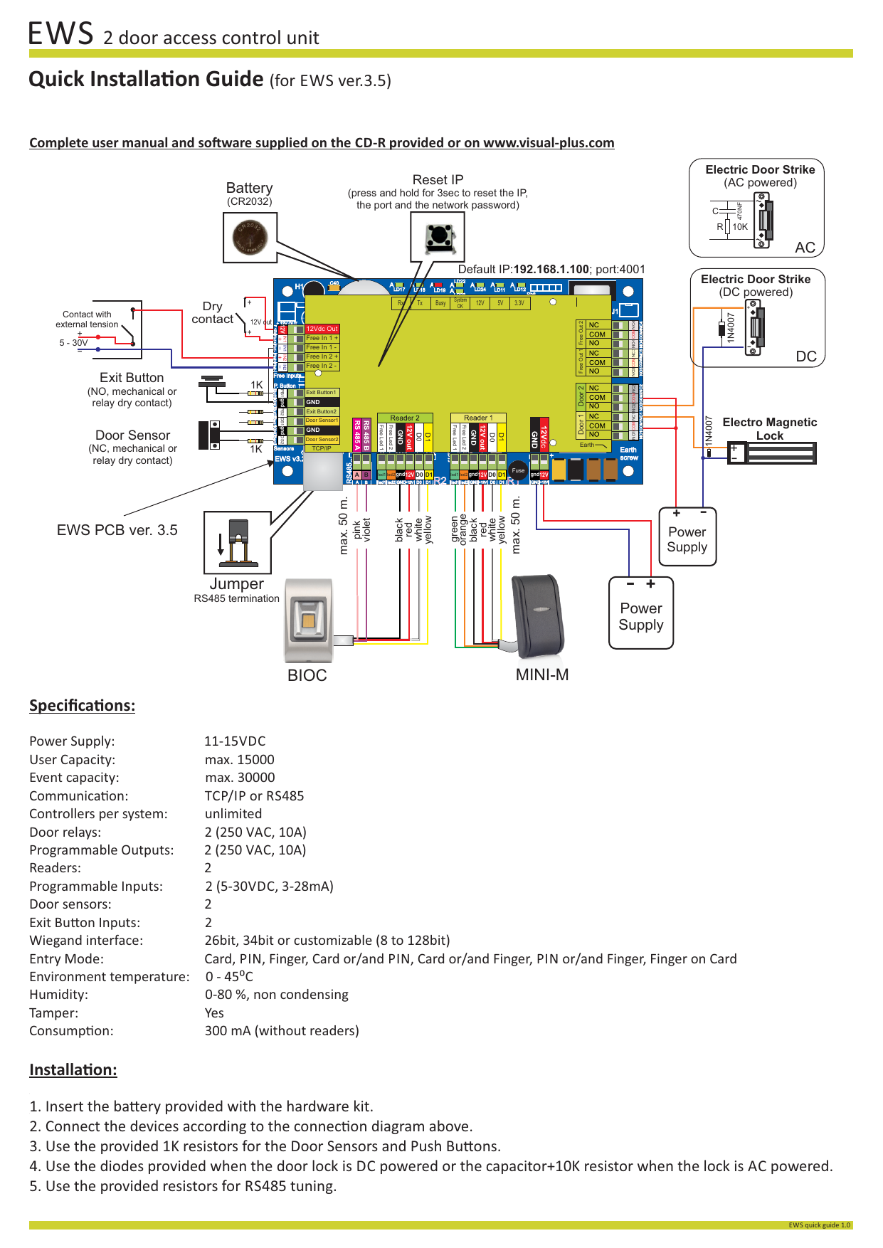
As a result of the isolation gap on the pcb layout, unwanted current loops may radiate. The impedance control allows for the pcb transmission lines to match the characteristic impedance of the cabling that is typically used.
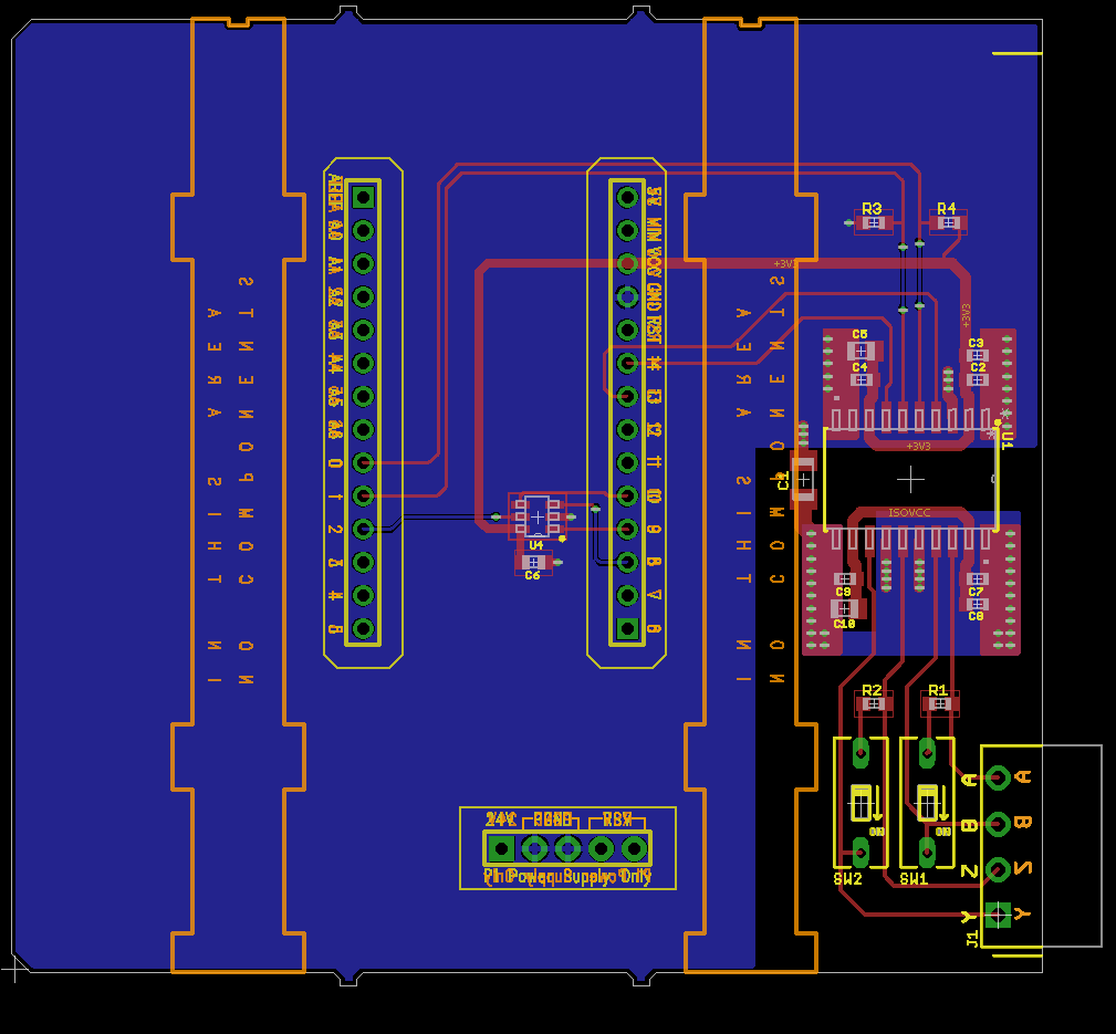
An Isolated RS422 / RS485 Shield for the Automation
For architectural reasons, we have a need to take a twisted pair (of an rs485 bus) into a pcb and then out.

Rs485 pcb layout guidelines. Having more than one driver accessing the bus simultaneously leads to bus contention, which must be avoided at all times. Via counts should be ideally minimized and backdrilled (no need to use blind/buried vias), and if you do your layout/routing properly you won't need vias for repeated layer transitions. Rs232 to rs485 converter, rts controlled.
This project demonstrates designing an electronic project using theprotel autotraxpcb cad package. Pcb layout and design, some principles. •use 45° bends for pcb traces.
The stubs connected to this differential trace pair in the pcb are very short ( pcb</strong> differential trace pair impedance to that of the twisted pair cable (~120 ohms)? •use at least two vias for each connection to the vcc or ground planes to reduce via inductance. All slave nodes communicate only with the master node.
Ftdi# 160 2 usb hardware design practices 2.1 trace style (matched pair, controlled impedance, length) usb requires two signals to make a single connection. In today's pcb layout, board space is at a premium. For most data transfers, when one is high, the other is low.
Keeping impedance, coupling, and length of your traces within spec is much easier when your pcb design software includes controlled impedance routing features. •place decoupling capacitors close to all active components, such as transceiver, voltage regulator, and mcu. Adhering to some basic electromagnetic suppression guidelines and concepts during pcb layout mitigates radiated emissions.
Make sure also to have the appropriate semiconductor companies review the portions of the design that utilize their components, or follow their application and design guidelines. The reason for this is to minimize the parasitic capacitance effects between the pcb traces and layers of the pcb because this reduces the filtering benefits of the ferrites. For now, let's look at how these three common protocols can be used in your pcb layout and some important points to maintain signal integrity.
Multiple layer pcb boards and routing lean heavily upon vias for maximizing the density to increase the system's feature set while decreasing the system's size. The pcb traces would add about 2 cm (just less than an inch) of length to the bus. The pcb layout around the l1 and l2 ferrites.
Figure4.suggested pcb layout with ground and vcc layers isl3152e tvs rs rs = vcc vias = ground vias to bus connector Isolation is implemented on the printed circuit board (pcb) with split reference planes separated by a physical isolation gap. There is a way of usingblank components as drawing.
Design guide v1.1 9 their own design checklist. Maxim has integrated both data and power isolation in a tiny module. The project starts with an emptycircuit sheet and shows the selection and addition of components.
Also, the density of their placement on the pcb is continually increasing. Use a 3rd party firm that specializes in m2.com carrier board development. The network is connected so that the master node communicates to all slave nodes.
Pcb layout and component selection are of paramount importance when designing. The keep out area means there must not be a gnd 2 fill or any metal fill on any layer underneath the ferrites. This document is a guideline for designing a carrier board with high speed signals that is used with toradex computer modules.
An_146 usb hardware design guidelines for ftdi ics version 1.1 document reference no.: Ics, including tvss, are designed to be very compact. Contact your m2.com module vendor.
Layout design guide toradex ag l altsagenstrasse 5 l 6048 horw l switzerland l +41 41 500 48 00 l www.toradex.com l info@toradex.com page | 2 issued by: Protection devices and pcb layout guidelines to enhance an application's immunity in electrically noisy environments and survivability of emi, emc, eft, and esd events as described in the international electrotechnical commission (iec) standards:

Rs485 Pcb Routing Guidelines PCB Circuits
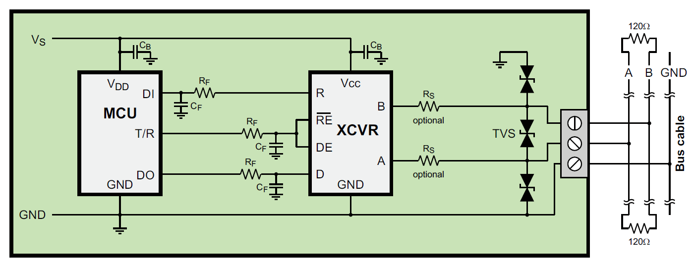
How to solve MAX485 heating and stops working problem

R 485 Daisy Chain Wiring Diagram

Rs422 Pcb Routing Guidelines PCB Designs
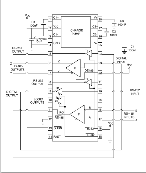
R 485 Daisy Chain Wiring Diagram
Rs485 Wiring Diagram — UNTPIKAPPS
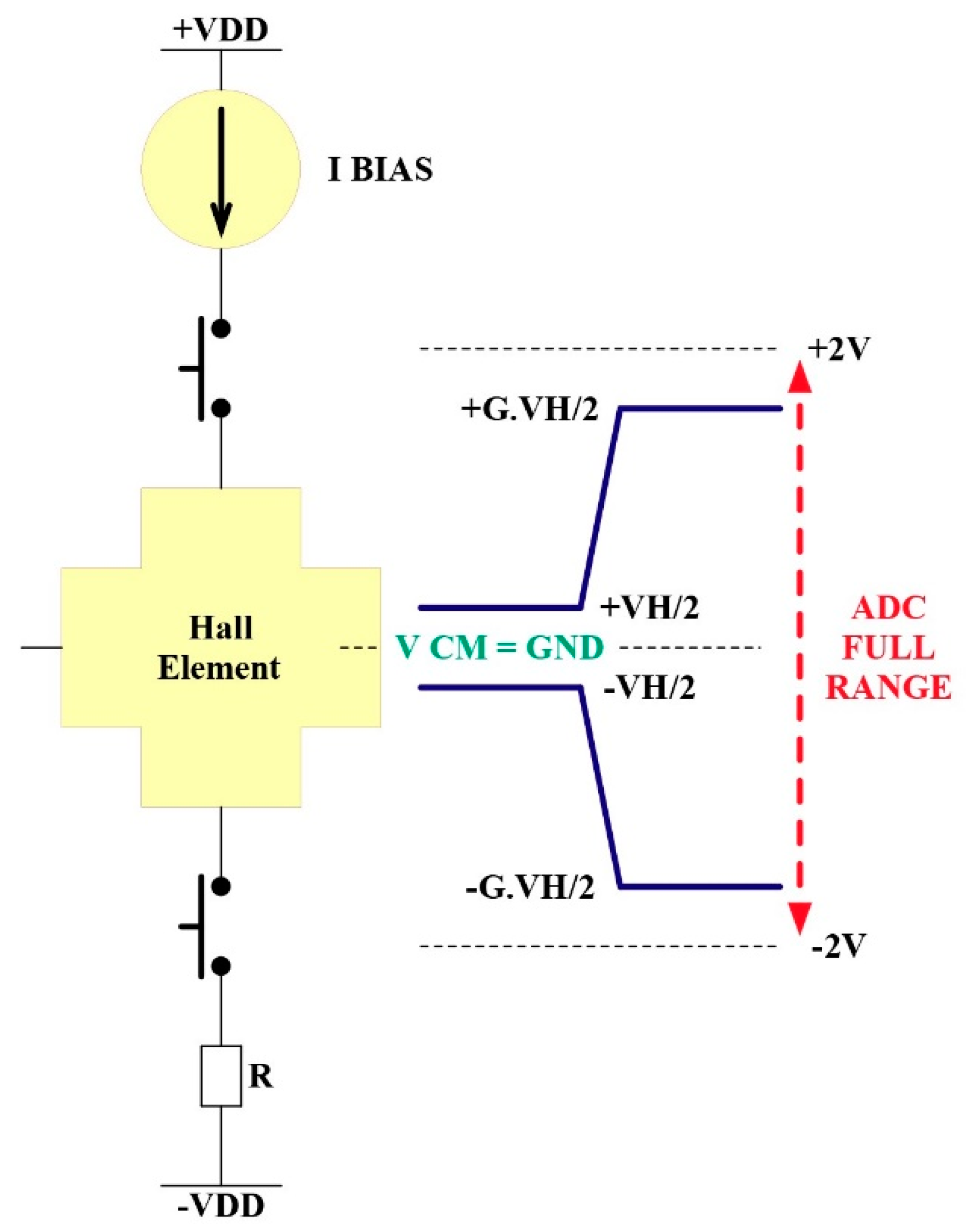
Rs485 Pcb Routing Guidelines PCB Circuits

DC2364A Reference Design RS232 Interface
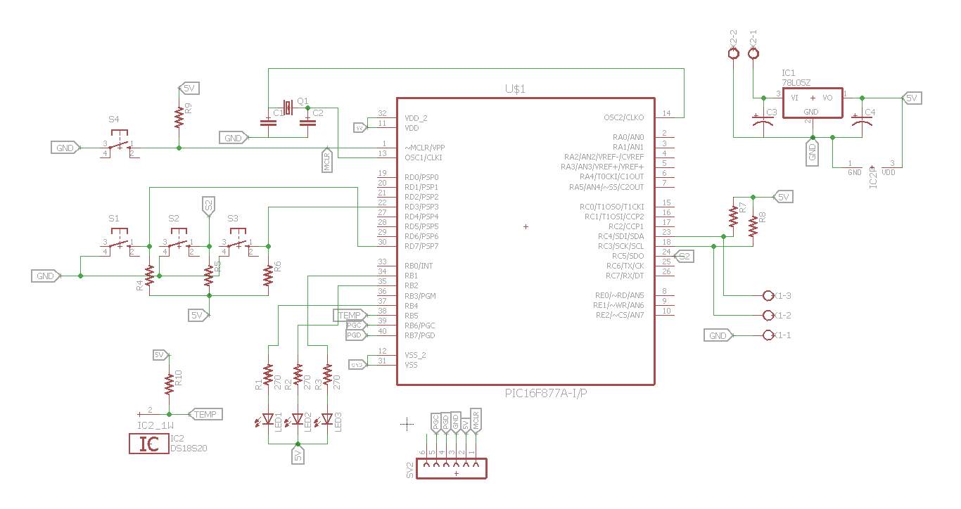
Rs485 Pcb Layout Guidelines PCB Circuits

LTC1334_Typical Application Reference Design RS485
Rs422 Pcb Routing Guidelines PCB Designs
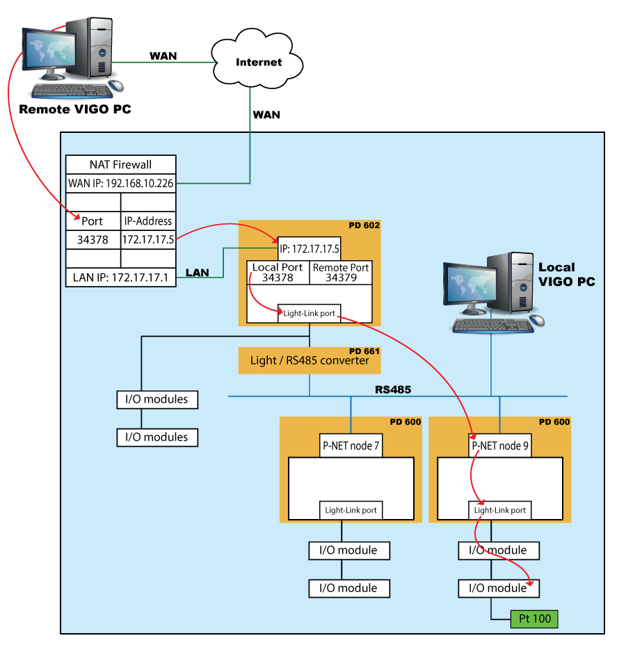
Rs485 Routing Guidelines PCB Designs
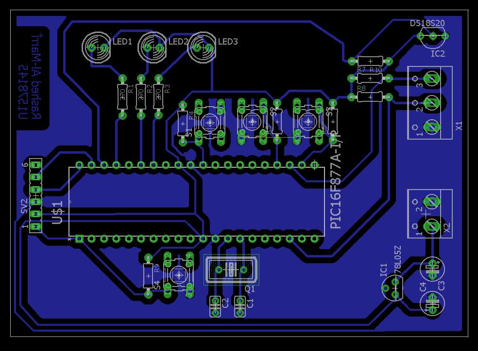
I2c Pcb Layout Guidelines PCB Circuits

Rs422 Pcb Routing Guidelines PCB Designs

Rs485 Pcb Layout Guidelines PCB Circuits
Rs422 Pcb Routing Guidelines PCB Designs

Guidelines for Proper Wiring of an RS485 Network
